
- Home
- Entire Malaysia
- Selangor▼
- Home Appliances & Kitchen
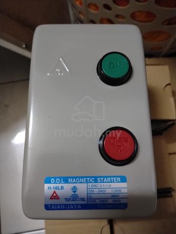
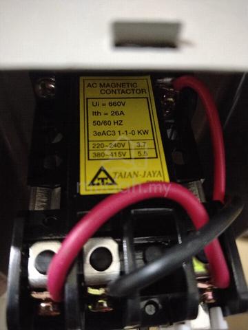
- TAIAN-JAYA C-16L1 contactor.
TAIAN-JAYA C-16L1 contactor.
List-ID: 11517673708 Jul 15:03
Description
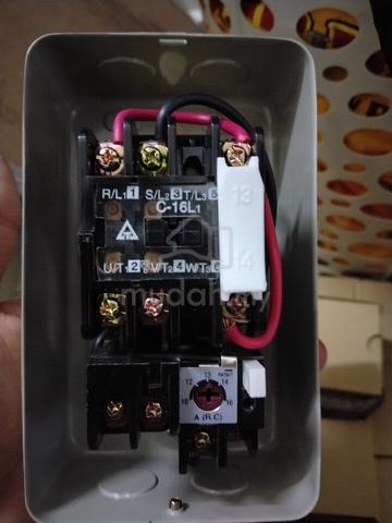
- Terminals: Clearly labeled line inputs (R/L_1, S/L_2, T/L_3) at the top and load outputs (U/T_1, V/T_2, W/T_3) below them.
Auxiliary Contact: A white auxiliary block labeled 13 and 14 is attached to the right side.
Control Wiring: Pre-wired loops (a black wire and a pink/red wire) connect the main power lines to the control coil and auxiliary circuits.
Thermal Overload Relay: Attached directly to the bottom of the contactor to protect the motor from overheating.
Current Adjustment Dial: Features a red adjustable dial ranging from 10A to 16A (set near 13A-14A) to calibrate the trip current.
Reset Mechanism: Includes a white manual reset plunger next to the dial.

Mudah Safety Tip
If it is a meet-up/COD, always inspect item condition on site before paying. Find out more safety tips in MudahSafety!
Do you find this ad suspicious or inappropriate?
Report this ad (List-ID: 115176737)Is this your ad? Manage it using these links.
You May Also Like





Price
RM 50
Location
Selangor - Seri Kembangan
Shortlist, compare, decide — faster on the app.
Scan QR to Download App


4.7
200K+ reviews
Share this ad